
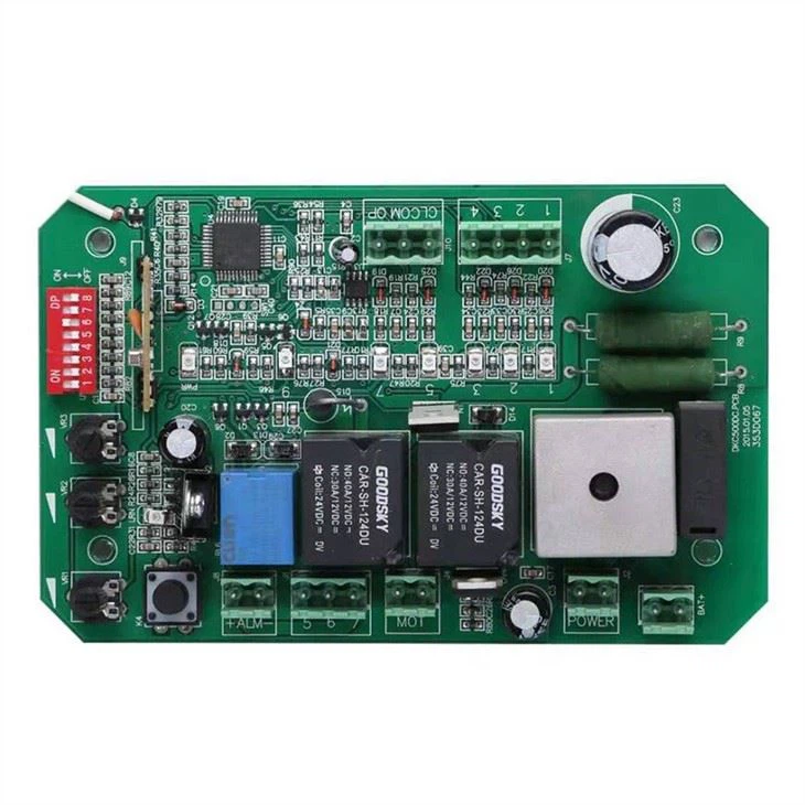

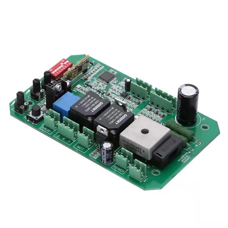

DKC500DC DC Door Motor Control Board
1.24VDC 2.PCB BOARD MATERIAL -- FR-4. COMPATIBILITY--The control board is only compatible with our remote control. You can ask us before you make an order. 3.AUTOMATIC CLOSE TIME SETTING--3s, 10s, 30s. 4.REMOTE CONTROL--For this control board,you can add 40 remote controls.(if you need the remote control,you can choose it from our store.) 5.EASY TO INSTALL AND SETUP--You can install and setup by yourself according to the instructions easily.
Installation
DKC500DC/DKC800DC sliding gate opener is applicable to gate weight less than 600kg/800kg, and length of the sliding gate less than 12m. The drive mode adopts the rack and gear transmission. This gate opener must be installed inside the enclosure or yard for protection.


Transformer Power Input Connection
Wiring instruction:
J1 Terminal
5 COM (GND)
6 Photocell input (N.C.);
7 Extra power input +24VDC
J2 Terminal
Connect to 24VAC(Fig.11 shows 120W 230VAC/24VAC annular transformer connection)
BAT+ Terminal
Battery interface
J4 Terminal
DC motor wire connection (Red wire to top, black wire to bottom)
J7 Terminal
1 Gate open control button (N.O.);
2 Gate close control button (N.O.);
3 Stop control button (N.O.);
4 Control button common terminal;
J8 Terminal
24V DC caution light
J10 Terminal
OP Open limit switch;
COM Limit switch common terminal;
CL Close limit switch;
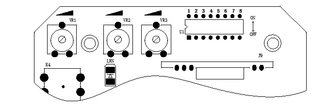
Adjusting knob
VR1: For motor working total time adjustment. Clockwise rotation to increase, counter-clockwise rotation to reduce. The total time can be set to 10 seconds as minimum and 90 seconds as maximum. For example, if gate moves 20 seconds, please try to add 5 seconds, namely setting 25 seconds is suitable.
VR3: For motor auto-reverse force adjustment when meeting obstacle.
Clockwise rotation to increase the reverse force, counter-clockwise rotation to reduce.


Send Inquiry